Quantcast
Channel: ArduPilot Discourse - Latest topics
Viewing all 46087 articles
Browse latest View live

Please an answer on external I2C and Canbus on P2.1

$
0
0

@Corrado_Steri wrote:

Hello, as the title says i really am confused about external I2C and canbus on Pixhawk 2.1.

Should they already work on 3.5.3? they shouldn't? I read different opinions and read different things about fixes to be released on github comments.

Would a dev please let us know (maybe interests someone else too) what is the current deal on external I2C on Pixhawk 2.1 and about Canbus? All of this on AP 3.5.3

Thank you very much,

Corrado

Posts: 1

Participants: 1

Read full topic


Crash due to (SAFE) mode

$
0
0

@robothornet wrote:

Hi everyone,
we are using several Pixhawk 2 powered fixed-wing UAV (with a Here+ GNSS) for atmospheric research. Generally, the Cube performs very well and the handling and flight characteristics improved greatly compared to our old system. However, today we had the first crash. We flew a grid in 75 m relative altitude and everything went fine until suddenly the message (SAFE) appeared in the HUD and the plane started losing altitude. Switching to manual mode did nothing and the plane crashed because we couldn't regain control. While reading the logs, I couldn't find any reason for the crash. Can anybody here take a look at the logs and maybe help me find the reason for this behaviour?
the logfile

Posts: 1

Participants: 1

Read full topic

Help reading LOG after crash

$
0
0

@Bog_Dan wrote:

Hello,
My drone is china f450 with apm 2.6 and 1000kv motors. I've been struggling to tune it last week and today I finnaly got some stable results but close to end of my testing the drone just flipped in Stabilize mode and broke 1 arm and propeller.
Is getting very frustrating after finnaly tuned it to just flip and crash by itself.
Please if anyone can discover some good information in my flight log or tell me how to check what was wrong. I'm new with APM trying to figure it out.

I uploaded .bin log here https://files.fm/u/855833ph

Auto analyze restults :

Log File C:\Users\Underground\Documents\Mission Planner\logs\QUADROTOR\1\2017-11-07 14-57-39.log
Size (kb) 2692.1513671875
No of lines 36721
Duration -1 day, 23:13:19
Vehicletype ArduCopter
Firmware Version V3.2.1
Firmware Hash 36b405fb
Hardware Type
Free Mem 0
Skipped Lines 0
Test: Autotune = UNKNOWN - No ATUN log data
Test: Brownout = FAIL - Truncated Log? Ends while armed at altitude 8.54m
Test: Compass = GOOD - No MAG data, unable to test mag_field interference

Test: Dupe Log Data = GOOD -
Test: Empty = GOOD -
Test: Event/Failsafe = FAIL - ERR found: CRASH
Test: GPS = GOOD -
Test: IMU Mismatch = UNKNOWN - No IMU log data
Test: Motor Balance = FAIL - Motor channel averages = [1380, 1365, 1581, 1586]
Average motor output = 1478
Difference between min and max motor averages = 221
Test: NaNs = GOOD -
Test: OpticalFlow = FAIL - 'FLOW_FXSCALER' not found
Test: Parameters = GOOD -
Test: PM = GOOD -
Test: Pitch/Roll = GOOD -
Test: Thrust = GOOD -
Test: VCC = UNKNOWN - No CURR log data

I calibrated the motors before flying I don't know why they still unbalanced. Can that be the crash reason ?

Thanks I appreciate your help.

Posts: 1

Participants: 1

Read full topic

Questions re building Ardupilot on Windows 10 / WSL / Ubuntu / bash

$
0
0

@wkf94025 wrote:

Thanks to some very clear directions here on how to build Ardupilot in the new Windows 10 "native" Linux subsystem ("WSL"), I was able to install WSL, make, gcc, et al, clone the master locally, and build it with no apparent errors. I haven't flown the resultant hex, but am fairly confident in the results, and saved the entire dialogue.

Now I want to clone a different branch off master, and build it. It's night_ghost's HAL port to the Revo Mini class of FCs. I can't tell who authored the WSL how-to doc, but thank you. Is it possible someone could give me a few hints as to how to then compile an alternate branch of Ardupilot (just ArduPlane, actually), having successfully built the master? According to night_ghost, the following should work:
1. download code from original Ardupilot (done)
2. go to Arduplane folder (done)
3. make px4-v2 (done, although via "./waf configure --board p4-v2", and "./waf plane")
4. after successful build download my [night_ghost] sources and then move ".git" and "modules" folders from official to my sources.
5. Go to Arduplane folder in my sources
6. make revomini

I am having some problems with the above steps, and thought I'd post here in parallel with further trial-and-error. If anyone can guide me to a robust recipe for achieving this, I would be grateful. I am also planning on modifying the source locally and rebuilding, but one step at a time.

Background: former C developer decades ago, plenty familiar with source control, dependencies, make, unix, etc.

Thanks,
Kelly

PS: if "Dev" is the wrong topic, please guide where better to post this...

Posts: 1

Participants: 1

Read full topic

Erle Hexacopter’s accelerometer and compass fails to calibrate through QGroundControl

$
0
0

@shubham wrote:

Hi,

While calibrating the Erle-Hexacopter, I am getting Calibration Successful as the message but the AccelRange is coming out to be critical. This is the message I am getting:

Also, the Compass calibration isn't geting completed after Compass 1 gets calibrated. I am rotating the Copter along all the axes, the status bar for Compass Calibratin is full but the message shown is keep rotating.

I have ArduPilot 3.4.0dev installed on the Erle-Brain 3.

Thanks,
Shubham

Posts: 1

Participants: 1

Read full topic

Sky Viper finally in the UK

Best Connection for DroneKit + APM Planner (Intel Nuc)

$
0
0

@edean wrote:

I am new to the Ardu Pilot world. While flying the a copter with APM Planner2 on Ubuntu, I would also like to have an Intel Nuc with a DroneKit connection to query for flight parameters to construct some metadata along for some other business logic.

It seems the best way to do this is just with a serial to USB connection and connect the Nuc to telemetry 2 (while AMP will connect via telemetry 1.

Does this seem like the best option/does anyone recommend a better option?

Posts: 1

Participants: 1

Read full topic

Can not Geotagg Pictures With Mission Planner

$
0
0

@dronesurvey wrote:

Hi, I was hoping someone can help me with this. I am trying to Geotag Pictures with Mission Planner. For some reason, it does not recognize the time of when the pictures were taken,; although it is very clear that the property is ttime is stamped in every single picture as seen in Windos File propertites. Does any one know why?

Posts: 1

Participants: 1

Read full topic


SkyViper V2450GPS at Costco in Australia

Arducopter\Pixhawk hardfault on bootup (custom firmware)

$
0
0

@nbrakeES wrote:

I uploaded a customized version of the ArduCopter 3.5.0 code and am getting a hard fault during boot-up that prevents me from connecting through the USB to flash a different firmware.

Here's what I'm seeing
1. Plug pixhawk into computer using USB
2. FMU pwr - solid green, FMU B/E - flashing orange
3. Windows device manager recognizes newly attached COM 3
4. COM 3 disappears from windows device manager AND FMU B/E - SOLID orange

When I connect to the pixhawk using the FTDI cable to the Serial 4/5 interface I observe the same behavior and the PX4\PIXHAWK terminal in Mission Planner reports the following:

SeAssertion failed at file:armv7-m/up hardfault.c line: 184 task: init
...[additional error information]

How do I get the pixhawk reset so I can flash different software to it? (I'm under a bit of a time crunch on my contract so any help is GREATLY appreciated)

Posts: 2

Participants: 2

Read full topic

Alexmos and Storm32

$
0
0

@pyrate wrote:

Will the Mavlink documentation work as well on serial with an Alexmos as it does with the storm? I have seen some pictures that had Alexmos on the board case but the chips say storm 32 on them.

Would one be wise to only go with the Storm confirmed boards?
Or will Alexmos gimbal boards work just as well?
I know they are more expensive, but the extended encoder version looks a lot simpler to wire to encoders, which I plan to use

Posts: 1

Participants: 1

Read full topic

Status extra led

$
0
0

@Henrymunoztorres wrote:

Hello, I would like someone to help me with a question, I have a 2.8 apm, with firmware 3.2, the doubt is that today lit a led that I think I have not seen before, apparently for what I read would be the extra status led, one red color that is near the usb port, I do not know what it means, thanks for the help.

Posts: 1

Participants: 1

Read full topic

ArduCopter firmware in STM32F4 Discovery

$
0
0

@Jungoo_Park wrote:

Hi guys, We have tried to make quadcopter drone in Ubuntu 16.04 for a few weeks. Actually, We can't afford a new PX4 controller, because it's so expenssive to us... That's why we try to make a copter to use our STM32F4 Discovery. By the way, I have some questions.
1. How can I firmware to my stm32f4 discovery controller from the open sources(https://github.com/ArduPilot/ardupilot.git) ?
2. Is it possible to configure between stm32f4 discovery controller and APM or Mission planner ?

Posts: 2

Participants: 2

Read full topic

Copter-3.5.4-rc1 has been released for beta testing

$
0
0

@rmackay9 wrote:

Copter-3.5.4-rc1 has been released for beta testing so you should be able to download it through the Mission Planner (and perhaps other ground stations) from the Install Firmware screen after pressing the "Beta Firmwares" link.

The changes vs Copter-3.5.3 are in the ReleaseNotes.txt and also copied below:

  1. Compass improvements:
    • support added for QMC5883L, LIS3MDL, IST8310
    • COMPASS_TYPEMASK parameter allows enabling/disabling individual compass drivers
  2. LightWare and MaxBotix range finders supported on both I2C buses
  3. Serial port 5 can be used for telemetry or sensors (previously was only for NuttX console)
  4. px4pro flight controller supported
  5. TradHeli fixes:
    • motor runup check applies to all flight modes (previously only loiter, poshold, althold)
    • swashplate behaviour changes when on ground in acro, stabilize and althold
    • servo test function fixed
    • direct drive fixed pitch tail fix
    • Z-axis Accel P gain default lowered to 0.3
  6. EKF origin set using SET_GPS_GLOBAL_ORIGIN mavlink message instead of SET_HOME_POSITION
  7. Intel Aero supports 921600 baud rate between main flight controller and companion computer
  8. Bug fix to I2C race condition on Pixhawk that could occasionally cause I2C device to not be detected

The real push for this release comes from the compass changes. The popular Honeywell compass (HMC) has become nearly impossible to find so the manufacturers of the Pixhawks and GPSs are moving to other brands of compass.

You'll also see a number of TradHeli issues have been resolved. This is thanks to Chris Olson, Bill Geyer and Tridge over the past month or so. Thanks!

If all goes well with the beta testing we will release this in a week or so as the official version.

So please, beta test this version and provide feedback here in this thread or preferrably in new threads in this Copter-3.5 section if you find problems. Thanks in advance!

Posts: 5

Participants: 3

Read full topic

UnATRaP - Part 9: Electronics Bay and Wiring

$
0
0

@Georacer wrote:

2017-11-02 17.18.22

So far this blog series has been involved with the mechanical aspects of the UnATRaP platform and while these are as important here as in any mechanical system, electronics have a very significant role in robotic platforms. We started touching on the topic last time with the power supplies and today we proceed to the core, discussing autopilot and avionics.

During the design phase, the idea was to have a semi-permanent installation of the core electronics in a dedicated compartment/bay, separate from any interchangeable payload. We selected the cavity at the back of the cabin, because it had a clean rectangular shape but also was the least accessible location of the cabin.

The Porter has a fairly tall interior; should we lay our electronics flat on the floor we would waste a lot of internal volume. For that reason, we went for a vertical layout of the various components.


A Nice Rack

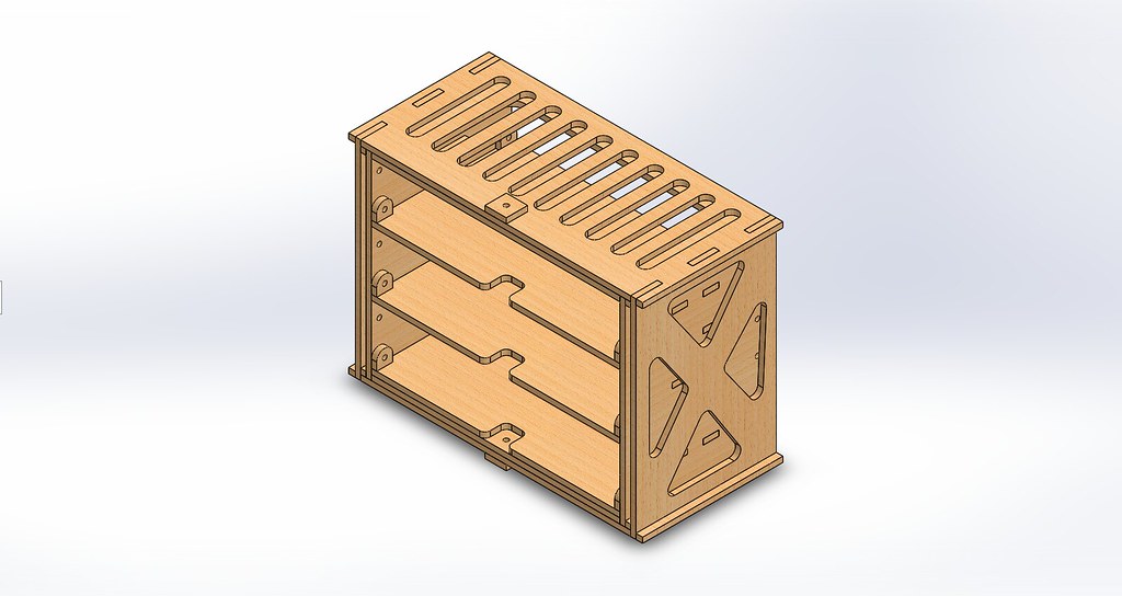
We wanted to go for a rack-like solution, which should be firm but at the same time removable, for ease of access in times of repair and upgrades. It should have independent shelves so each could host a notionally separate part of the circuit. With our favourite material (plywood) and our favourite tool (laser cutter) we designed and built the autopilot rack.

electronics_bay

2016-04-15 15.36.12

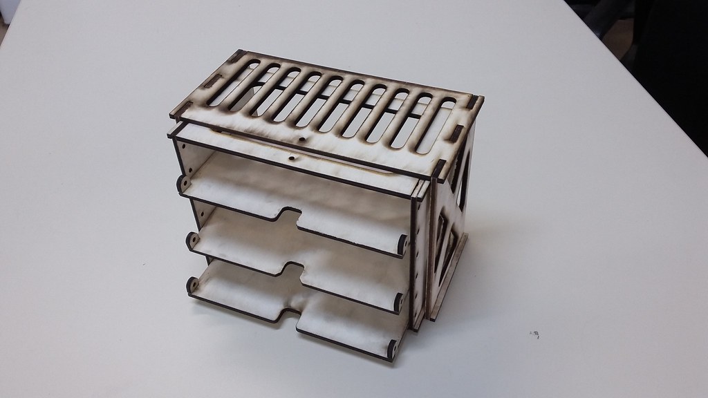
The plywood parts were assembled with CA glue. Each shelf can slide inside the rack and is individually screwed in place with hex screws and blind nuts.


Groundwork

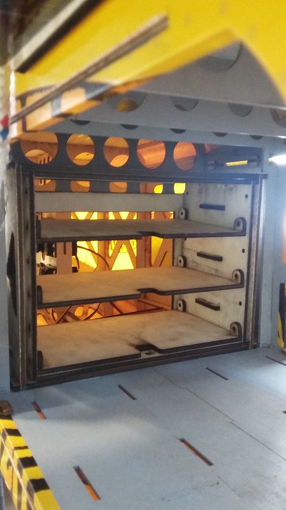
For the rack to be removable, glue or nails were out of the question as mounting options. Instead, we built an enclosing rectangular structure, which would be permanently mounted on the back of the cabin. The electronics rack can slide in and out of it while maintaining alignment with the airframe body axes.

The final position is fixed with two hex screws, going into embedded blind nuts.

2016-04-15 15.37.24


The Shelves

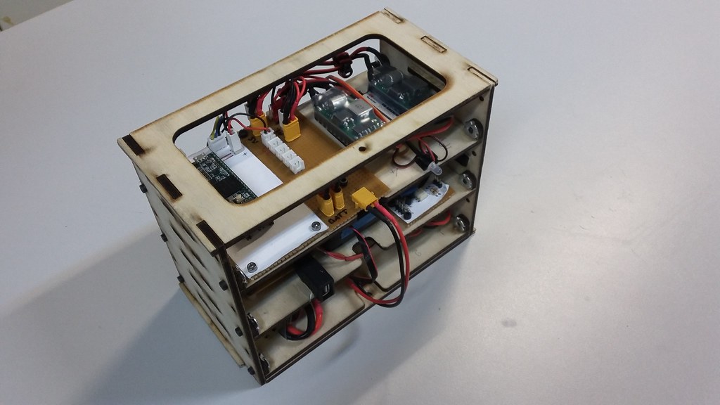
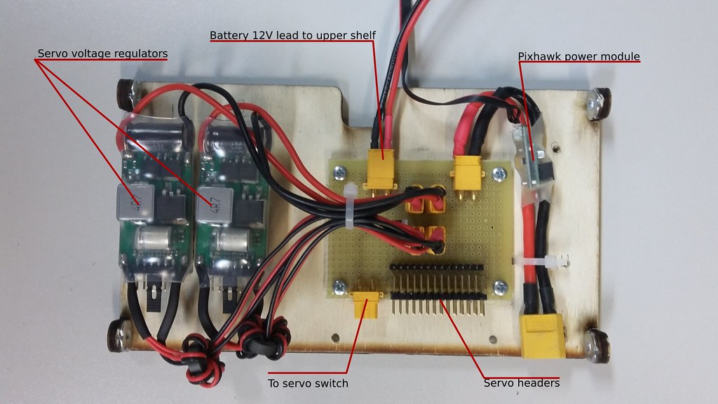
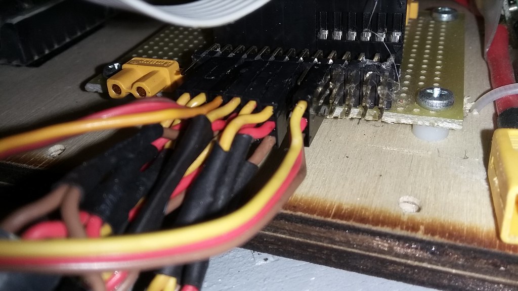
Okay, so let's move onto populating each shelf. The bottom one hosts the Pixhawk power module, the redundant servo rail power supplies (see previous article) and the distribution board for the servo signals. XT30 connectors were used extensively, since technically the classic DuPond connector can't handle more than 1A continuous.

lower_shelf

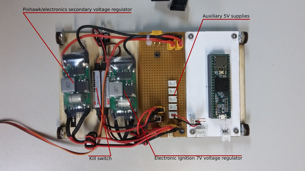
On the top shelf you can see the BEC powering the electronic ignition, the kill switch and the BEC for the secondary Pixhawk voltage supply.
A general purpose 5V rail for various electronics (mainly used for things mounted on the wings) has a central position.
The random Teensy 3.5 isn't part of this article: it has been used to convert some digital measurements onto analog voltage to be fed to the Pihxawk's ADC and is now deprecated.

top_shelf

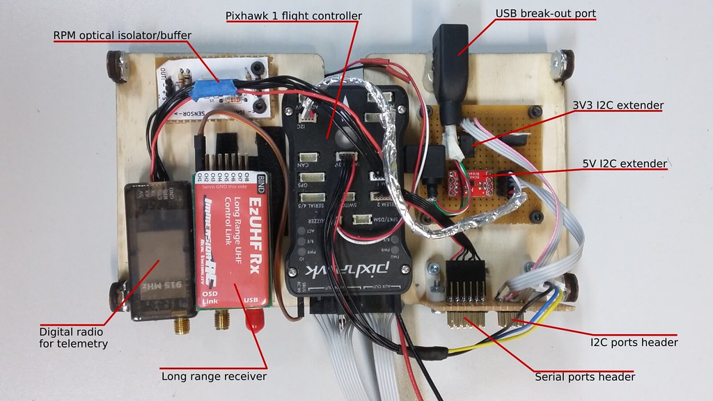
The middle shelf is were the real deal is: The Pixhawk 1 has a central position, to allow for as close an alignment with the longitudinal axis as possible.
The PPM input is connected to the LRS receiver (ezUHF brand). However, the kill switch signal (channel 2) goes directly from the receiver to the kill switch. We didn't want the Pixhawk to have any say on the status of the ignition.
The telemetry radio is normally connected, nothing fancy here.
A USB extension chord has been permanently mounted on the board, to allow for easy access to Pixhawk's USB port. Inserting a USB cable to pull the DataFlash log while the electronics are stored in place on the field is extremely hard. This solution makes the process a lot easier.
On the top left you can see a board with with paperscreen. It is an optically isolated RPM signal buffer which feeds readings to the Pixhawk and will be covered in a future article.
To the right, you can see the I2C and Serial ports broken out to standard 0.1" pin headers, for ease of access. The Serial ports are directly passed through, but some I2C headers are pre-buffered with range extending ICs, some with 5V logic and some with 3V3. More on these on a future article as well.

middle_shelf


Wiring

External connections to the rack have been implemented in a number of ways.
All servo cables were routed to a single point behind the servo header array. Traditional 0.1" pin headers were used, secured with hot glue.
XT60 and XT30 connectors were used for high-amperage situations, without any further securing.
RF connections are done with SMA connectors, secured with hot glue. We have found that they severely degrade with time, becoming too loose for comfort.
Small signal applications, such as the RPM, are using 0.1" pin headers, which may or may not be glued down, depending on the situation.

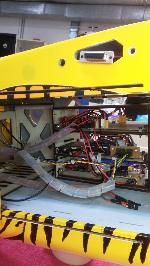
Most cable groups were wrapped with plastic spiral for logical clarity and neat packing.

2017-11-03 10.54.46

2017-11-02 17.10.35

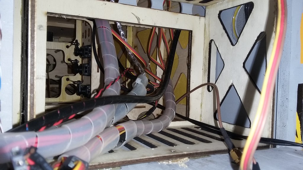
Cables going to the back of the fuselage were not an issue in routing. The wings and front section were a bit more tricky, though. We needed to be able to unscrew and pull the rack forward and to the side, for access to the back connectors. Also, we didn't want any connectors on the front of the rack. Keeping all the connectors to one side has the advantage that you can remove any shelf separately from the rest by unplugging its cables.
Those two specifications combined result in all the cables being routed to the back of the rack.

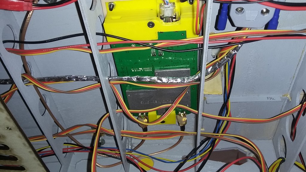
As a result, any cables going to the front of the fuselage and the wings were routed behind the rack, upward to the ceiling and over the rack. Thankfully, the Porter has nice circular channels on its ceiling.

2017-11-03 10.54.31

Also, in order to be able to pull the rack to the front and side, we needed to allow for enough cable overhead length.

2016-12-04 19.37.48


This approach worked wonders for us. The electronics are easily accessible, monitorable, stable, securely packed and modular. There was one significant downside with it, though.
The selected installation location was quite far behind the center of lift. Considering all of the structural parts, cables and components weight a significant amount, it isn't surprising that we needed a lot of ballast to balance out the plane.
This has become a problem for us, especially during the last flight where extra payload was carried: the airframe was clearly at the limits of its loading capabilities. It would require more power, have less top speed and it would land too hot.
To improve this situation, we are currently migrating all the power supplies in front of the fuel tank, on the front section of the fuselage. We hope that this will save us up to a kilogram of weight.


This concludes this part of the UnATRaP blog series. If you have comments or recommendations, please let me know. Until next time!

Previous article: Part 8: Power Systems

Posts: 1

Participants: 1

Read full topic


Stall speed and landing in FBWA

$
0
0

@weliwarmer wrote:

Hi,

I had two stalls on two different planes (big A tail and Skywalker X5) while they were running Auto missions. They both stalled on a sharp turn, last-but-one waypoint on different days and in different wind conditions.

I increased the ARSP_FBW_MIN and TRIM_ARSP_CM by 3m/s and ran the same mission to test. All went fine with take-off, mission and landing perfect.

Unfortunately, now when I land the A tail using FBWA, the airspeed drops below the 12m/s and the stall prevention kicks in dropping the nose - into the ground!

I know FBWA has enhanced stall prevention so my questions are:
Should FBWA be avoided for landing?
Are there other settings that would allow low risk landing on FBWA?
Other than Manual and Auto, what modes are recommend for landing?
Can I go back to -3m/s but increase the turn speed so it does not stall?

ArduPlane 3.8.2 on Pixhawk 2.1 with Here+. I'll dig out the logs if helpful.

Thanks, Tim

Posts: 6

Participants: 2

Read full topic

Trouble assigning channels to transmitter

$
0
0

@Seatsport58 wrote:

Hi all, struggling to assign channel 7 which is landing gear on Futaba t14sg. Need to configure in Mission planner too. Thanks

Posts: 1

Participants: 1

Read full topic

Obsolete EMI Filter replacement?

$
0
0

@MikeLemon wrote:

Hello there,

I'm designing now an open source Carrier board which has the goals of beeing cheaper and integrate the buzzer into it as well as having the old px2 ports for the users who want to remain with some of the px2 hardware instead of buying the expensive PCNC compatiable producs.

Now in the PCNC schematics you can see an EMI filter conected to each connector on the board but when you go look for the manufacturer number of it noone supplies it anymore...
Anyreason why is that?

Thanks for helping!

Posts: 2

Participants: 2

Read full topic

MP mag calibrate does not work with EKF2 enabled in 3.6dev

$
0
0

@mike wrote:

Not sure where to post this so just let me know if there is a better thread elsewhere. Using Copter 3.6dev with UAVCAN compass and GPS module. I can see the data coming in on the status screen of Mission Planner so I know that the compass is working but the Mission Planner compass calibration does not even see the external UAVCAN compass or the internal either. This is Arducopter v3 on a Solo. So I had two Pixhawk cubes and found one worked and one did not. I diff'ed the parameter files for each and found that the one that did not work had EKF2 enabled and the one that calibrated fine had EKF2=0. One of the versions of 3.5 that I was testing must have changed the default to EKF2 enabled because I did not set it myself and when I loaded 3.6dev it did not reset the parameters.

I read that EKF2 is now default enabled since some version of 3.5.x but with it enabled I can not use Mission Planner to calibrate the mag. If I turn it off the mag cal works normally.

Posts: 1

Participants: 1

Read full topic

Another PH2.1 + ProfiCNC Power Module Thread

$
0
0

@Chris_Hardwick wrote:

I'm new to Pixhawk 2 and I'm setting up the ProfiCNC power module for the first time. I can calibrate the voltage easily enough, but the current is another matter.

My setup: PH2.1 with ProfiCNC power module, TBS Disco, 4S 5200mAh LiPo, Firmware APM Copter V3.5.3, MP version 1.3.50.3 beta.

I've tried selecting the ProfiCNC HV Power Module in MP. It consistently reads 1-2 Amps low, across the range of 1-20 Amps. I've tried selecting "Other" for sensor type. I can pick a current set-point and get an accurate current reading at that point, but nowhere else. It seems to me that my use-case is not uncommon. I'm not sure why I'm having difficulty with this.

I've also noticed that only the motor current draw shows up in the calculated current. With PH1 and the old 3DR power module, I would see a draw around 1.2 Amp, sitting on the bench, with all on-board electronics powered and running. Does the ProfiCNC power module regulator connect to battery power before or after the current-sense resistor?

I'm also having a hard time finding self-help information about this power module. Is it open-source, or has the project changed direction? If I could find a schematic and BOM for the power module I could probably figure out the voltage-current multiplier and offset. Otherwise, I'm just flailing around.

If there is another way to manually calibrate this sensor, I'd love to know. I have access to a full microelectronics design verification lab, with calibrated electronic load, precision meters, 'scopes, etc.

Many thanks in advance for any information!

Chris

Posts: 1

Participants: 1

Read full topic

Viewing all 46087 articles
Browse latest View live


<script src="https://jsc.adskeeper.com/r/s/rssing.com.1596347.js" async> </script>