Quantcast
Channel: ArduPilot Discourse - Latest topics
Viewing all 46468 articles
Browse latest View live

Telem2 and Compass led´s issue

$
0
0

@scubari wrote:

hi. yesterday i installed benewec TFmini lidar unit, its working fine and is connected to Telem2 port. There seems to be some sort of conflict with compass indicator led´s. When lidar is connected to the cube, i get no Led´s on my dual Here+ units, only red light on the safety switch. If i disconnect Telem2 its all good again with led lights. I have Cube black on latest offical fw.

Edit. All this in bench.Copter was not armed at any point!

Posts: 1

Participants: 1

Read full topic


Arduplane with jet engine - looking for experiences

$
0
0

@Eosbandi wrote:

Hi !
Are the any experiences with Arduplane driving a plane with a jet engine ? How can it handle the slow throttle response? Any specific recommendations?

Posts: 3

Participants: 2

Read full topic

FC Mount Geometry & Options

$
0
0

@1piece wrote:

My traditional Heli has a rotor shaft with a 5° forward cant as part of the design. Unfortunately the flight controller mounting plate does NOT have a matching 5° forward cant.

Should I mount my Pixracer flight controller with shims to match the rotor mast cant or can the 5° difference be adjusted out or compensated for via software? (I also plan to mount the FC upside facing downward due to fit and access considerations).

Per Chris Olsen’s video 2 on set up, I know i must shim the Heli skids so that the main bearing block is level during QGC setup and programming. What about the FC?

  • I will make sure the FC is level (albeit upside down) during initial calibration but after that, can I initialize for take off with the FC not level or will I have to shim the Heli for each take off?

Thanks to all.

Posts: 1

Participants: 1

Read full topic

Cannot conect Rover 4.0.0 Beta to Orange Cube [Solved]

$
0
0

@Morten_Westeraa wrote:

Hi guys.

I have a brand new Orange Cube on a mini carrier board. I use Mission Planner.
I have flashed the Rover 4.0.0 Beta firmware to the Cube, this goes very smooth.
After firmware upload I cannot connect to the Cube.
My windows pc sees the com port (port 13), but if i try to click connect, a window pops up saying
“Connecting Mavlink timeout in 30 seconds”.
After timeout a message comes up: “No Heartbeat Packets Recieved”
Any ideas?

Thanks in advance😊

Posts: 2

Participants: 1

Read full topic

Where would I change vectored thrust mixing in the source code?

$
0
0

@jumpwing wrote:

Im building a 2 meter flying wing VTOL (tricopter tiltrotor) where all 3 motors tilt as follows;
in MC mode - front 2 motors for yaw & pitch - aft motor for pitch control
in FW mode - front 2 motors for roll & pitch - aft motor for thrust only

I could use some help on what files in the source code that I would need to alter to accomplish this.

here is a link on YouTube showing a guy that has coded this (and has not released working firmware) https://www.youtube.com/watch?v=WMh8BiOLrns

he has a QQ group in China but I can not join it (I think I need to use We-Chat). If anyone can please let me know.

Here are the related links:

Dropbox link with all of his builds and docs. It is being updated but is not well organized
https://www.dropbox.com/sh/ircqhf6phsgagk3/AAA_Cw3VwoHm2o_viCWHZJj9a?dl=0

His documentation & his “QQGroup” in China that “Kris” said helped develop this flight model

A store that is selling parts for the build. No replies from my emails.
https://vtoluav.weebly.com/skywalker-x8-vtol.html

But if anyone knows what files I would need to look at in the source code please let me know

Note - I have posted this subject before. It is being restarted for the purposes of forming a group to look into it further.

Thanks

Jeff

Posts: 1

Participants: 1

Read full topic

ARM + GPS OK Output

$
0
0

@prokopcio wrote:

Hi,
I change controller from APM to PIXHAWK, it works much better but i need outputs for be sure that controller is Armed and GPS is in good condition.

in APM i had such outputs:

but i can’t found this potion in PIXHAWK.
I need signal on AUX output when main led on pixhawk light solid green.

Posts: 1

Participants: 1

Read full topic

QGC "Missing params: - 1:FLTMODE6“... its because of the" boat" option (frame class)

$
0
0

@Origin wrote:

Hi everyone,

I have a PixHawk 2.1 Cube Black with Ardurover 3.5 & QGC on my computer

I just found a weird bug: when the FRAME_CLASS option is set to 2 (“boat”), QGC cannot load the parameters correctly anymore and send this message:

Parameters are missing from firmware. You may be running a version of firmware QGC does not work correctly with or your firmware has a bug in it. Missing params: -1:FLTMODE6, -1:FLTMODE5, -1:FLTMODE4, -1:FLTMODE3, -1:FLTMODE2, -1:FLTMODE1

see attached screenshot:
Bug_firmware_corrupted|690x176

The way around this bug is to set back FRAME_CLASS to 1 (“rover”)

I am curious about what caused a bug liked that, and because I actually spent quite some time debugging this I want to make sure no one is in the same situation as me before :slight_smile:

Cheers !!

Posts: 3

Participants: 3

Read full topic

Display AGL altitude in qgc

$
0
0

@moreba wrote:

Hi
we have AMSL alt of vehicle , also qgroundcontrol can recieve terrain alt from internet before flight or during flight , and we can calculate AGL altitude .
The least advantage is that we have AGL alt and can manually take action if needed.

Posts: 1

Participants: 1

Read full topic


Nmea data on serial port

$
0
0

@sparkyincali wrote:

I see now in plane 4.0 there is an option for the serial ports to output nmea data. I tried finding information on this on the wiki but didn’t find it. I was wondering if there was anything else needed to make this work other than setting the option for the uart and speed. I am trying to use the MFD telefly tiny to encode the data for my tracker and it accepts nmea input. On my 405wing which is using a bn180 gps using ubx. I tried setting the serial option and baudrate for 38k and the telefly didn’t register any input. I hooked only the rx of the telefly to the tx of the controller and the ground also. Any ideas on if there is a step I missed and if this is truly nmea output.

Posts: 2

Participants: 2

Read full topic

Protecting against pilot error when switching to stabilize with the throttle down

$
0
0

@rrr6399 wrote:

I am adding some logic to my GCS to detect flight mode changes and then try to recover if a non-automatic mode like stabilize or loiter is used with the throttle too low by switching to guided or brake. (If there isn’t an RC, the throttle is automatically set to 50%.) Running against the simulator (SITL), I noticed that the copter will not switch into guided or brake if the mode is switched to stabilize with the throttle at minimum. The copter just plummets to the ground even if I start at 100 m or so. The only way I’ve seen to recover is to raise the throttle. If I use Loiter, the logic of switching to guided works fine. I don’t want to override the RC throttle since the pilot expects to fly it with the RC for this case.

I haven’t tried this on a real copter yet, but wondered if anybody knew why the flight controller won’t recover by switching immediately into guided if the mode is switch initially to stabilize with the throttle down?

Also, would this type of logic be useful in flight controller itself? Many pilots have crashed their copters by forgetting to raise the throttle before switching to loiter or stabilize.

Posts: 1

Participants: 1

Read full topic

Unlimited range HD streaming with LTE Part 2

$
0
0

@DomenicoPatella wrote:

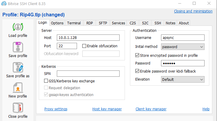
If the installation of Apsync is completed and everything work , connect to the WiFi network Apsync
Open Bitvise
Username /Password : apsync

Press log-in and enter in termimal mode , we need to know the name of ethernet device

immagine

Add static IP address on Ethernet port

sudo nmcli con add type ethernet con-name ‘eth0’ ifname enxb827eb249e28 ip4 192.168.99.55/24

LTE MODEM

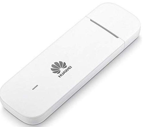
immagine

The USB LTE E3372 modem is detected as a virtual network device.This makes the initial setup easy.
I previous tested the internet connection on my notebook.
I will not write how to configure the USB dongle , in my case the APN were already configured

The command nnmcli device will show ithe new device "Wired connection 2 "

immagine
Try ping to google

apsync@apsync:~ $ ping www.google.com
PING www.google.com (216.58.198.4) 56(84) bytes of data.
64 bytes from mil04s03-in-f4.1e100.net (216.58.198.4): icmp_seq=1 ttl=51 time=78.3 ms

Now RPI is connected on internet

ZERO-TIER
Go to https://my.zerotier.com/
Create an account and network

Copy your private ID , will be necessary to write it when the client will join your network

Install your client in your PC /Tablet/Smartphone
Join the client and your network

Now we can install zero-tier on RP

curl -s https://install.zerotier.com | sudo bash

Launch service

sudo zerotier-cli join xxxxxxxxxxxxxxxx ( YOUR ID )
200 join OK

Now you are registerd on your VLAN

Go to your account , the list will be show your device online

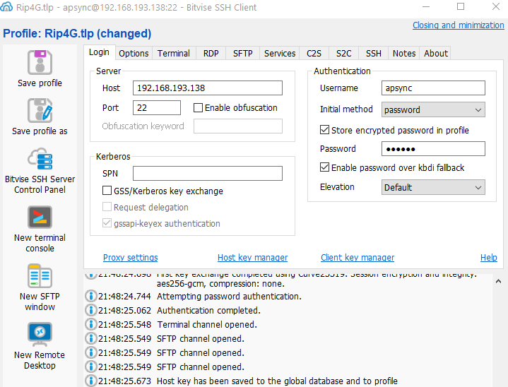
Write name and IP Address , check to enable

Check from console

apsync@apsync:~ $ ping 192.168.193.138
PING 192.168.193.138 (192.168.193.138) 56(84) bytes of data.
64 bytes from 192.168.193.138: icmp_seq=1 ttl=64 time=0.154 ms

Now Apsync have a static IP address on ZeroTier network

Reboot raspberry and try to connect with VPN address

Well at this step you can reach Apsync everywhere

GROUND STATION

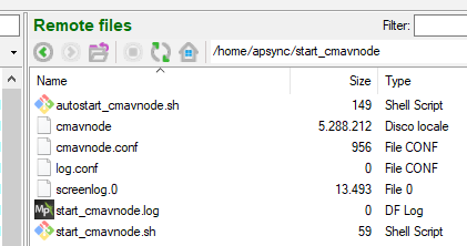
In SFTP Window go on /home/apsync/start_cmavnode

immagine

Edit cmavnode.conf

Go to section and add [to_pc]

[to_14550]
    type=udpbcast
    sim_enable=false
    bcastport=14550
    bcastip=10.0.1.255
    bcastlock=1


[to_pc]
    type=udp
    targetip=192.168.193.131 
    targetport=14550
    sim_enable=false

Targetip is CLIENT STATIC IP ADDRESS PC or TABLET …

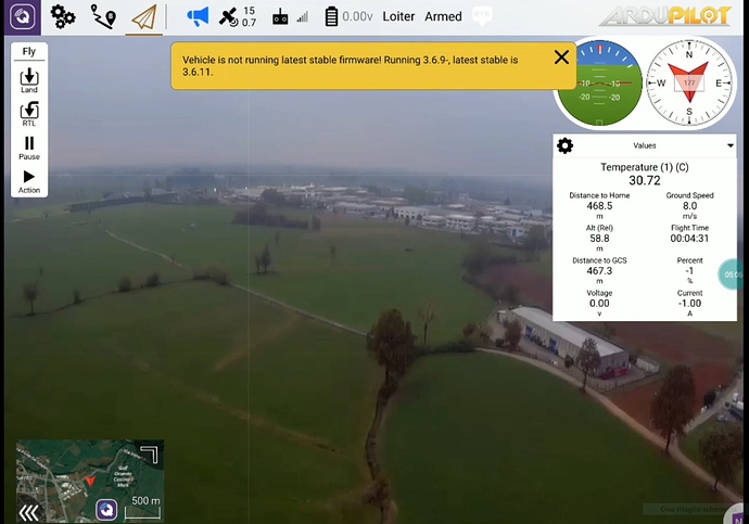
TEST VIDEO

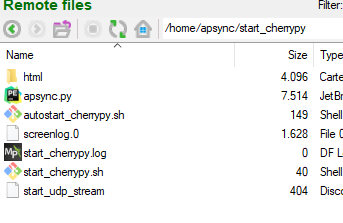
Go to home/apsync/start_cherrypy

immagine

Edit start_udp_stream

Comment section raspivid

 #raspivid -t 0 -h 720 -w 1024 -fps 25 -hf -b 2000000 -o - | \
    #    gst-launch-1.0 -v fdsrc ! \
    #		   h264parse ! \
    #		   rtph264pay config-interval=1 pt=96 ! \
    #		   udpsink host=$STREAM_TO_IP port=$STREAM_TO_PORT

Add function test_video

 function test_video {

gst-launch-1.0 videotestsrc is-live=true ! \
 video/x-raw,framerate=30/1 ! videoconvert ! \
 x264enc ! h264parse ! rtph264pay pt=96 ! \
 udpsink host=$STREAM_TO_IP port=$STREAM_TO_PORT       
 
}

test_video

Go to your client browser to RPI IP address port 8000
Start streaming

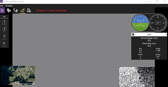
Open QCG

The gray glitches can be solved with rtpjitterbuffer
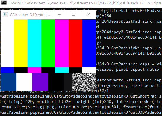
Try Gstreamer pipeline in your PC , in my case example:

d:\gstreamer\1.0\x86_64\bin\gst-launch-1.0 -v udpsrc port=5600 caps="application/x-rtp, media=(string)video, clock-rate=(int)90000, encoding-name=(string)H264" ! rtpjitterbuffer ! rtph264depay ! avdec_h264 ! videoconvert ! autovideosink sync=false

immagine

At this point the system is ready to connect FlighController over interner and send video

Next step i will try to explain how to use and V4L2 or Encoder H.264
Video first outdoor test

Posts: 1

Participants: 1

Read full topic

Building on Windows with waf and Eclipse -- wrong binaries produced!

$
0
0

@Marc_Dornan wrote:

I am trying to compile with waf through Eclipse. I have set up as per the instructions:
http://ardupilot.org/dev/docs/building-setup-windows-eclipse.html#building-setup-windows-eclipse

What is really odd as I am trying to compile for fmuv3 (Pixhawk/Cube) and waf seems to be creating binaries for the Omnibus F4V6. I am running the config for fmuv3 and then plane – see my screen shot.

But here is what is compiled – not for Pix Cube! See the Eclipse console:

20:41:15 **** Build of configuration Default for project ardupilot ****
“c:\cygwin64\bin\python2.7” waf plane
Waf: Entering directory `/home/marc/Ardupilot/build/omnibusf4v6’

What am I doing wrong here? I have no issue compiling to the correct folder in a Cygwin64 Terminal session, so what is wrong. Any pointers greatly appreciated.

Posts: 1

Participants: 1

Read full topic

Can not get telemetry to work with Frsky Passthru

$
0
0

@voi9viper2 wrote:

can someone answer a question about frsky passthru? I’m using the half duplex option and uninverted s.port from an r-xsr receiver. I hooked an FDT1 converter RX wire to the s.port wire, as well as power and ground, and ran a terminal program to capture the bytes. All the data is a start command (7E) followed by two or three bytes. I also added some gcs().send_text() messages to the AP_Frsky_Telem.cpp code, in the senduint16 and senduint32 methods, but these do not appear to ever run. The message scheduler messages I added do appear. Here is the captured data:
7e 2f 7e ef bf bd 7e 71 7e ef bf bd 7e 53 7e 34 7e ef bf bd 7e e2 90 96 7e ef bf bd 7e ef bf bd 7e 39 7e ef bf bd 7e e2 90 9b 7e e2 90 80 7e ef bf bd7e 22 7e ef bf bd 7e ef bf bd 7e 45 7e ef bf bd 7e 67 7e 48 7e ef bf bd 7e 6a 7e ef bf bd

I was expecting at least 6 bytes of data in each message, including a param id and 4 data bytes. Being a one wire interface I can really tell the data direction. Is this data just the reciever polling?

Posts: 2

Participants: 1

Read full topic

Mission Mode Reverse Behavior

$
0
0

@mkoos wrote:

Simple question: Does the autopilot try to make the rover go in reverse when conducting a mission?

If it doesn’t, then does that mean that the throttle channel simply stays between 1500 and 2000? I assume that since typically 1000-1500 is reverse, while 1500-2000 is forward. Thanks for the help in clarification!

Posts: 3

Participants: 2

Read full topic

Assign joystick axis (6&7) to Gimbal servo 10&11?

$
0
0

@Oeble_Huygen wrote:

Hi , Is there a possibility to assign joystick axis’s to do something with servo out ?. My joystick has 2 (extra) axis that show up in QG as axis 6 and 7 ( Dpad up/down and left right ) that i would like to use as tilt and roll control for my Gimbal . Is this possible ?.

Posts: 1

Participants: 1

Read full topic


Ground Station and Air Station not connecting

$
0
0

@ChaS2 wrote:

I am using 3DR Single TTL MINI Radio Telemetry 433MHz 250mW for PIXHAWK and APM for wireless communication between Ardupilot APM 2.8 and mission planner running on laptop. According to the LED status, It should show solid green when connection is established and blinking green when searching for connection.

Whenever the ground station is connected to the air station, we face different situations.

case 1 ) solid green light is established and after few minutes due to loss of communication, the green light continues to blink.

case 2) the blinking green light is observed, the communication between two telemetry ports isnt established in the first place.

What could be the possible issues?Why isn’t a solid connection being established?

Posts: 1

Participants: 1

Read full topic

Obstacle avoidance code

$
0
0

@Ahmad_Magdi wrote:

hello, i have a project where i need to program a drone using pixhawk 2.4.8 to avoid obstacles using a “radiation sensor” i am guessing the code should be the same as an obstacle avoidance with ultrasonic, i have no experiance in setting up the drone or programming the pix hawk i just want it to fly to specific waypoints and take a measurement if the measurement increases it should back off, i already have a tarrot fy680 frame with dji motors (e800) hexachopter. please help me with the code or set up. i am lost !!

Posts: 1

Participants: 1

Read full topic

Holybro Durandal

$
0
0

@mogu wrote:


Durandal is the latest update to the successful family of Holybro flight controllers. It was designed and developed by Holybro, optimized to run the latest Ardupilot firmware.
It features the latest advanced processor technology from STMicroelectronics®, sensor technology from Bosch® and InvenSense®, and a ChibiOS real-time operating system, delivering incredible performance, flexibility, and reliability for controlling any autonomous vehicle.
Durandal’s STM32H7 microcontroller, running at 400MHz, has 2 MB of Flash memory and 1 MB of RAM. With the increased processor power and ample resources, developers can freely implement more complex algorithms and models on the autopilot.
Dual high-performance, low-noise IMUs on board are designed for demanding stabilization applications. Data-ready signals from all sensors are routed to separate interrupt and timer capture pins on the autopilot, permitting precise time-stamping of sensor data. Newly designed vibration isolation enables more accurate readings, allowing vehicles to achieve better overall flight performance.
The two external SPI buses and six associated chip select lines allow for additional sensors and an SPI-interfaced payload. There are a total of four I2C buses: two dedicated for external use and two grouped with serial ports for GPS/compass modules.
The Durandal is the latest update to the successful family of Holybro flight controllers. The Durandal autopilot development kit is perfect for developers at corporate research labs, startups, and for academics. Durandal: the cutting edge autopilot.

Product Features
Integrated sensors temperature control
More computing power and 2X the RAM of previous versions
New sensors with higher temperature stability
Increased ease-of-use: pre-installed with the most recent Ardupilot firmware
More efficient vibration absorption system

Technical Specifications
• Main FMU Processor: STM32H743

  • 32 Bit Arm ® Cortex®-M7, 400MHz, 2MB memory, 1MB RAM
    • IO Processor: STM32F100
  • 32 Bit Arm ® Cortex®-M3, 24MHz, 8KB SRAM
    • On-board sensors
  • Accel/Gyro: ICM-20689
  • Accel/Gyro: BMI088
  • Mag: IST8310
  • Barometer: MS5611

Mechanical Data
• Dimensions:804520.5mm
• Weight: 68.8g

More details: www.holybro.com

Posts: 1

Participants: 1

Read full topic

Camera focus plane

$
0
0

@niko wrote:

Hi guys, pls help me about one case. When camera starts trigerring in mission focus of camera goes wrong. I always check focus of cam before flight, and do trigger cam now, and got nice photoes, but when plane goes to his mission, starts doing photos, something goes wrong with focus. Focus in manual mode, and stays on correct position (infinity). Camera on plane Sony a6000. Please help! thx everyone)

Posts: 1

Participants: 1

Read full topic

Precision Landing with Realsense T265 Camera and AprilTag - Part 1/2

$
0
0

@LuckyBird wrote:

1. Introduction

The GSoC 2019 project has added to ArduPilot’s arsenal full support for the Intel RealSense Tracking Camera T265 to be used as a plug-and-play Visual-Inertial Odometry (VIO) sensor to achieve accurate localization and navigation. Hence freeing up resources for the onboard computer to utilize for other high-level tasks, which would pave the way for even more amazing applications to be built upon.

We now have a suite of sensors at our disposal:

  1. Standalone 6-dof (200Hz)
  2. Accel (200Hz) & Gyro (62.5Hz)
  3. Dual fisheye monochrome (8-bit) streams @ 848x800 30FPS
    (For additional info, here is the device’s datasheet).

In this project, we wil try our hand at a very old topic: precision landing. In a nutshell, image stream from one of the T265’s cameras will be processed to detect AprilTag visual marker, then we will follow MAVLink’s Landing Target Protocol that is supported by ArduPilot to perform precision landing. We will do it without (part 1, this blog) and with Robot Operating System (ROS) (part 2).

Let’s get started.

2. Prerequisite

Hardware

  • A copter frame of choice.
  • An onboard computer capable of polling image data from the T265, thus USB3 port is required. The Up board is what I am using, but the Jetson Nano or RPi 4 are also suitable alternatives for low budget setup. Unfortunately, the Raspberry Pi 3 which was used in previous blog posts is not suitable for this project.
  • A downward facing Realsense T265 camera, with USB port pointing to the right of the vehicle. Different camera orientations can be used as well, however some modifications are involved.

Software

3. How does it work?

How to perform localization and navigation

The main script t265_precland_apriltags.py is built on top of the existing t265_to_mavlink.py script, the content of which is thoroughly explained in this blog post, so check it out for explainations on how to attain accurate localization and navigation.

How to perform precision landing

Here’s an overview of the steps needed to add precision landing capabilities to our system:

  • First, we follow the t265_stereo.py example to optain the undistorted images from T265 fisheye images, intrinsic and extrinsic params in OpenCV.


    Undistorted
  • Next, AprilTag detection algorithm is run on the undistorted images to obtain the tag’s pose relative to the fisheye lens. We will use the duckietown’s Python wrapper for AprilTag 3 to ease up the workflow in Python.
    Tag Detected

  • If the landing tag is detected in the image, precision landing is performed following MAVLink’s landing target protocol. For ArduPilot, only LANDING_TARGET fields relative to the captured image are supported.

Note: It is implicitly assumed that the camera’s x axis is aligned with the vehicle’s y axis (to the right) while the camera’s y axis aligned with the vehicle’s -x (to the back). This is the same as pitching the camera down 90 degrees from facing forward. If your camera is oriented differently, then a transformation is mandatory. For reference, here’s the T265’s coordinates (note the fisheye’s axes), whereas the FCU’s local frame is (X Forward, Y Right and Z Down).

4. Instructions

Prepare the tag

We will use the tag image as provided in rs-pose-apriltag sample in librealsense. Here is the link for the pdf.

Print the pdf file above on a letter size paper. The tag size (the black part of the tag) on the paper should be 0.144m. Fix the tag to some landing pad or fix the tag to the ground. Make sure the tag won’t get blown away when the copter is descending.

It goes without saying that the tag size and id can be anything according to your requirements. All you need to do is modify the corresponding params, which we will discuss later on.

A stupendous amount of other tag options can be found here.

Install AprilTag 3 library

Clone the official repo and install the library with:

cd ~
git clone https://github.com/AprilRobotics/apriltag.git
cd apriltag
cmake .
sudo make install

The default installation will place headers in /usr/local/include and shared library in /usr/local/lib. Python wrapper will also be installed if python3 is installed.

Install other required packages

pip3 install transformations
pip3 install dronekit
pip3 install apscheduler

Download the scripts

cd /path/to/some/directory
wget https://raw.githubusercontent.com/duckietown/apriltags3-py/master/apriltags3.py
wget https://raw.githubusercontent.com/thien94/vision_to_mavros/master/scripts/t265_precland_apriltags.py

chmod +x t265_precland_apriltags.py

Modify the main script t265_precland_apriltags.py

  • If you have sucessfully followed the VIO wiki, all of the params that you use in the t265_to_mavlink.py script can be brought over.

  • The following new params are related to AprilTag detection:

    • tag_landing_id, default is 0. We will only land on the tag with this id.
    • tag_landing_size, default is 0.144. This is the tag’s border size, measured in meter. Change it to your specific tag setup. Reminder: for AprilTag, the tag size is the dimension of the black part of the tag.
    • tag_image_source, default is "right". For the Realsense T265, we can use left or right camera. You might find it useful to choose the camera with the least obstruction in its view, for example the landing gear.
    • landing_target_msg_hz_default, default is 20. This is the rate at which the LANDING_TARGET MAVLink message will be sent to the flight controller. As noted in the MAVLink wiki, the rate depends on the landing speed and desired accuracy; start with rates between 10 Hz and 50 Hz and tune performance as needed.

Viewing the AprilTag detection image

If you have a monitor connected to the companion computer:

  • Run the script with visualization option enabled:
    python3 t265_precland_apriltags.py --visualization 1
    
  • A window will pop up, showing the already processed image. If the tag is in the image’s view, there will be the tag’s id and a bordering rectangle in the image as well.

If you don’t have a monitor connected:

You can view the image through the ssh connection with X11 Forwarding.

  • First, enable desktop sharing option on the companion computer, here’s an example. Depends on your setup, you might need to tinker around a bit.
  • Next, ssh to the companion computer from your host computer. Work best with Ubuntu host computer.
    ssh -Y <username>:<ip>
    
  • Now you can run the script with visualization option enabled:
    python3 t265_precland_apriltags.py --visualization 1
    

ArduPilot params

  • The params required to facilitate VIO flight are documented in this wiki.
  • Set the following parameters through Mission Planner (or other GCS) to enable the precision landing feature and then reboot the flight controller.
    PLND_ENABLED = 1
    PLND_TYPE = 2
    
  • Setup the vehicle with one of the flight modes to LAND.

Run the script

  • For serial connection: set udev rules in order to get the USB available and allow permission to serial:

    sudo chmod 666 /dev/ttyUSB0
    
  • When all params are set correctly:

    python3 t265_precland_apriltags.py
    

5. Ground and Flight test

Ground test

Hold the vehicle on top of the landing tag and check on your GCS:

Verify that ArduPilot is receiving landing_target data

  • In the ssh terminal: when the tag is in the camera’s view, there will be a stream of messages begin with INFO: Detected landing tag followed by the tag’s position in the camera’s frame.
  • Check that ArduPilot is receiving position data by viewing the topic LANDING_TARGET on GCS. For Mission Planner, press Ctrl+F and click on MAVLink Inspector, you should be able to see data coming in under Vehicle 1.

Verify that ArduPilot is receiving pose data

  • Similarly, check that the message VISION_POSITION_ESTIMATE is coming through to the flight controller.

Verify that ArduPilot is receiving confidence_level data

  • View the topic VISION_POSITION_DELTA on GCS, field confidence should show the remapped value of confidence level. The confidence level should start at Medium and change to High after

Flight test

  • For downfacing configuration of the Realsense T265, there is a problem with inconsistent yaw angle between runs. The temporary fix is to tilt the nose up a little, so that the camera is not facing flat down, when the script starts. Once the FCU starts receiving vision messages, the vehicle can be put flat on the ground.
  • Take-off and hover above the target.
  • When target is detected (see above about verifying that ArduPilot is receiving landing_target data), you can switch the vehicle to LAND.
  • If everything is working properly, the copter should move towards, then land on the tag.
  • As usual, be prepared to retake control if there are sudden unexpected movements (Change mode to Stabilize, AltHold or Loiter).
  • If all is well, some successful tests can be seen below:

6. Next time

We will explore how to achieve the same goal in ROS. Thanks to ROS’s modularity, the software components are really easy to learn and modify. However, not everything is ready-to-go for our use case, and some developments are still required on our part.

7. Useful links

Posts: 1

Participants: 1

Read full topic

Viewing all 46468 articles
Browse latest View live


<script src="https://jsc.adskeeper.com/r/s/rssing.com.1596347.js" async> </script>