Quantcast
Channel: ArduPilot Discourse - Latest topics
Viewing all 46292 articles
Browse latest View live

Need help with traditional helicopter setup

$
0
0

@Reza_Nemovi wrote:

Hi all,

I’ve managed to get most everything setup on my Trex 700e based on the documentations and videos offered on Traditional helicopters. There are some ambiguities such as getting a message after RC calibration stating throttle reversed in transmitter. I’ve tried the reverse channel 8 in the transmitter with no luck. I also tried reversing channel 8 in qgroundcontrol and still get the same message.

I am assuming that the RC calibration bars in the software should move right when given forward pitch but mine travels to the left, rest of the channels respond correctly. The helicopter’s swash responds correctly to my stick input and also the FC responds to helicopter movement by countering it. I’d appreciate it if someone can assist with getting past these 2 issues.

Thanks,
Reza

Posts: 4

Participants: 2

Read full topic


Mission planner gets stuck loading the parameters

$
0
0

@AngelAlbeniz wrote:

When connecting the drone to MP the parameter loading process gets stuck at the end with the parameter “STAT_RUNTIME”. This occurs with both the direct USB connection and the wireless telemetry connection. And, with both MP (1.3.70) and QGC (3.5.6).

Capture

I have tested this problem with two different quadcopters, one fitted with a Pixhawk1 and running AC 3.6.6 Nuttx and the other fitted with CubeBlack running AC 3.6.12 ChibiOs. The problem behaves in the same way in both cases.

I have noticed that if I flash any new firmware in the autopilot the problem disappears, but when loading a parameter list from a file the issue returns.

Any idea why this happens and how to solve it?

Posts: 1

Participants: 1

Read full topic

15 V to Payload?

$
0
0

@Marco_Casella wrote:

Hello everybody,

I was looking for a feasible solution capable to provide 15 V to my Payload.
Among all the possible devices I have tried to find an UBEC/SBEC capable to provide such a Voltage, but I have not been able to find it one over 12 V as output.

do you have an advice for this topic?

Nonetheless I have keept searching and eventually with the help of other collegues we have found this device

Do you think this solution is feasible?
Do you have other advices?

Best regards

Posts: 4

Participants: 2

Read full topic

S1000 PDB - How is this working?

$
0
0

@vyoufinder wrote:

How does the Power Distribution Board on the s1000 work? Is it like an engine, where it fires in a firing order? In other words, does it matter which esc is plugged into which port on the PDB?

The reason I am asking is I bought a used s1000 condition unknown. I was relieved when I found out that they had already moved the 8 arms around for ccw and cw motors to be in the right places, and the wires are right. It works. The strange thing is that when they moved the arms, they left the plugs plugged into where they originally were on the PDB. So each motor main power connector is stretched to the opposing one next to it. Can I move the wires to route more as intended, or do they need to be plugged in like spark plugs, with some outputs on the PDB being used for CW or CCW or something.

Posts: 1

Participants: 1

Read full topic

How to compose MAVLINK_MSG_ID_TERRAIN_REQUEST message

$
0
0

@Pogo wrote:

Hi,

I’ve written a packet sniffing program in C that sits between ArduPilot and X-Plane and relays packets back and forth. It’s working well, but now I need to inject a MAVLINK_MSG_ID_TERRAIN_REQUEST message intended to go to the GCS (sysid 255, comp 190) as if it had been sent by the drone (sysid 1, comp 1). Then I await the GCS’s response. However, I must be doing something wrong because the GCS won’t send me the MAVLINK_MSG_ID_TERRAIN_DATA message.

Here’s my method for TCP, and perhaps you could tell me what I’m doing wrong:

First, I compose a message like this:

mavlink_message_t msg;
mavlink_msg_command_long_pack(1, 1, &msg, 255, 190, MAVLINK_MSG_ID_TERRAIN_REQUEST, 1, 338974514, -1176074192, 100, 1938953243, 0, 0, 0);

Then I send it to the GCS:

uint8_t injectbuf[1024];
uint16_t len = mavlink_msg_to_send_buffer(injectbuf, &msg);
size_t bytes = send(gcs_sockfd, injectbuf, (size_t)len, 0);

That’s pretty self-explanatory, I think. I hope someone can help!

Pogo

Posts: 2

Participants: 1

Read full topic

Battery call out

$
0
0

@Totalrebel142 wrote:

Hi there. Could anyone tell me how to get mission planner to call out the battery voltage as it does with waypoints and so forth. Also, i dont know where to set the battery voltage to turn red as soon as it reaches a certain voltage.

Thanks

Posts: 1

Participants: 1

Read full topic

Can someone explain trim throttle?

$
0
0

@xingxing wrote:

Hi guys, what is the difference between trim throttle and trim airspeed? my F405 WING flight control, flashed arduplane3.9.9 firmware, without airspeed sensor, I set trim throttle in 45%, trim speed at 15 meters, but in the air, the trim throttle sometimes drops to 30% to 40%, trim speed is not accurate in setting values.
can someone explain more details about this parameters

Posts: 1

Participants: 1

Read full topic

Omnibus F4 Pro PWM 7 and 8


Armed but it won't start

NTUN missing from logs, Loiter tuning

Crash after autotune

$
0
0

@Gyorgy_Fodi wrote:

Hello!

Yesterday I went to have a maiden flight with my newly built quadcopter. It’s using a pixhawk cube, on the latest arducopter firmware.
The flight was stable, went to fly few circles without a problem, than I set up the autotune.
After tuning one axis, I got the notification on the ground station, autone is done, and in the same moment, the drone started to descent aggressively.
What I saw in the log file, is a radio failsage, but everything is hard wired, receiver has its own 5A bec, and it has a telemetry. Ground station didn’t warn me about a telemetry or signal loss, so I think the power is fine.
After the crash, I checked everything, and did a second axis tune, where the exact same thing happened, atutune done, and the same moment it crashes.
Can somebody check the log, and suggest something?
Thank you!

Posts: 1

Participants: 1

Read full topic

Plane roll and crash at takeoff (auto)

$
0
0

@Dronotique wrote:

2019-12-20 13-04-02.zip (644.3 KB) 20191219_Save_W2000.param (18.5 KB) Hello,

I’m testing my first plane with last version of Arduplane.
When I made an auto takeoff it’s roll over on the left and crashed.

I’ve checked before in FBWA and auto mode and the surfaces move in the right direction (when I roll the plane on the left, the left aileron goes down and the right up, rudder and elevator are ok also).

Could you tell me what’s wrong.
I need help, I don’t understand what happens!!!

Thanks

Posts: 1

Participants: 1

Read full topic

Noob Rover: No servo output

$
0
0

@butchalline wrote:

My set up:
MP 1.3.7
Rover 4.0
Pixracer with buzzer, no switch
Known good servo and motor
Confirmed 5 VDC on servo output rail.
Armed and calibrated

Flight view > actions > raw sensor view > radio:
In this screen, the green bars follow throttle and aileron stick movements. See below:

MP%20servo%20out

But in initial setup > mandatory hardware > servo output:
Green bars do NOT follow stick movement. See below:

I do not know why Ch.3 shows a half bar as output. It is static on both screens.

So the big question… How do I get servo output to work?

Any and all help appreciated.

Posts: 1

Participants: 1

Read full topic

Antenna Tracker - Step By Step Setup and Simulator

$
0
0

@Itmac79 wrote:

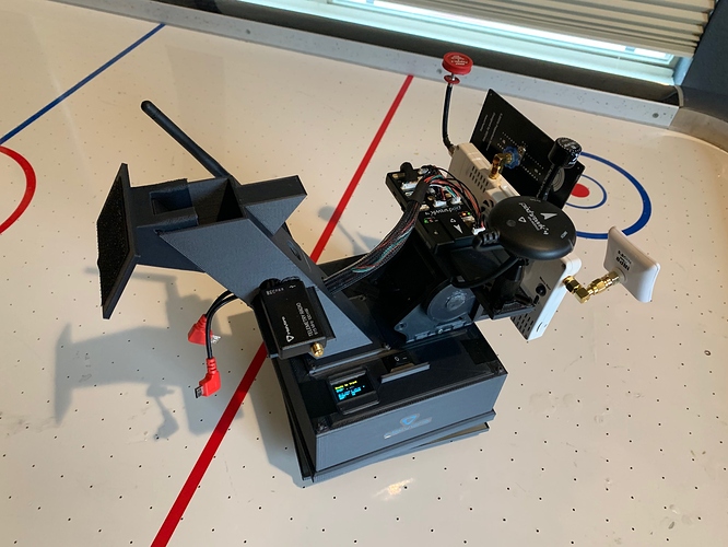
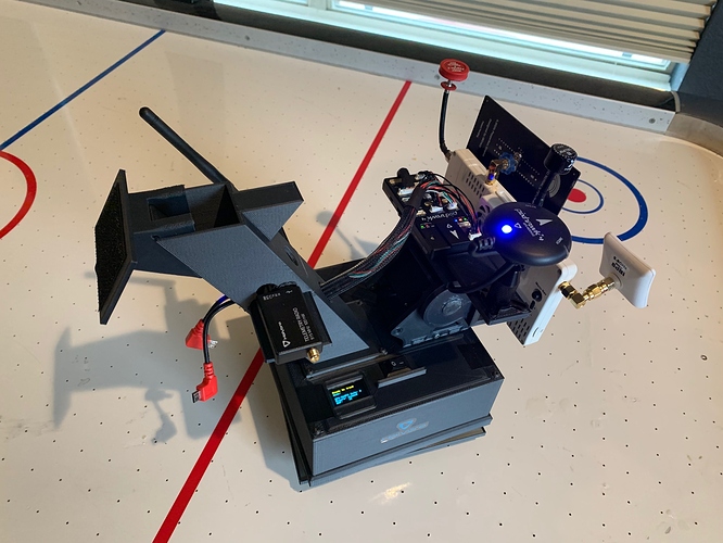
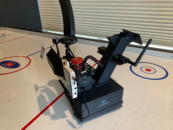
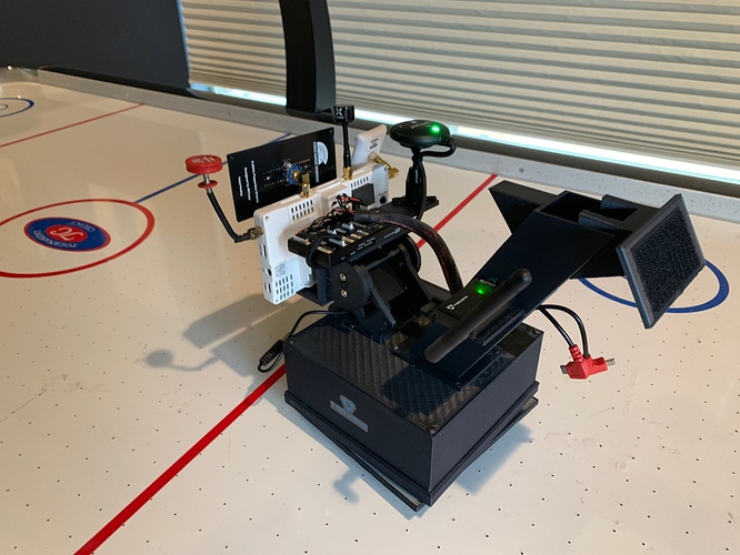
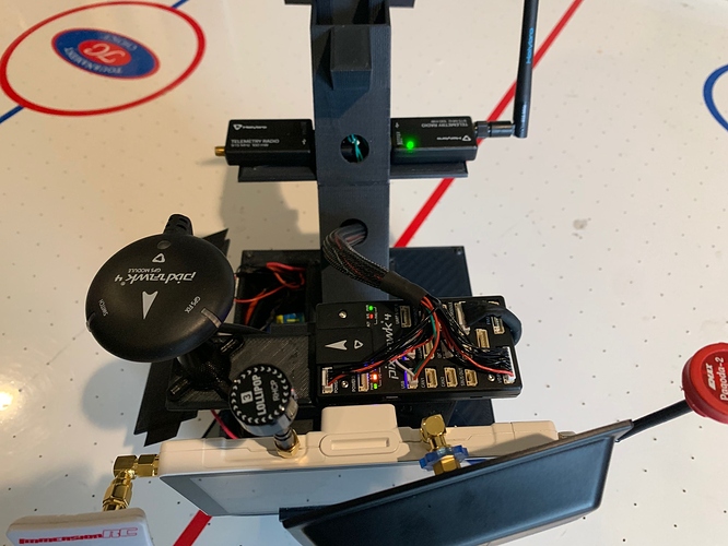
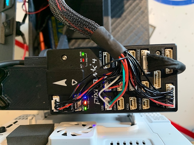
Documenting this will be an ongoing project. I will add to it whenever I have time. PLEASE feel free to contribute! The more insight the better! I know there are a ton of people out there that have tried and just given up when trying to make an AT and get it to work.

After fighting for weeks to get AT to work, I finally got it. Since there is limited detailed documentation on AT, I figured I would start putting together a step by step guide to what worked for me, and some key items that are critical for it to function properly that may not be immediately apparent to those of us with limited experience with Ardu/PX4. I know just about nothing about any of this and really learned and figured it out through this project and forum. Unfortunately, most of the others who responded to any of my posts for help, seemed to have the same issues, thus why I am doing this.

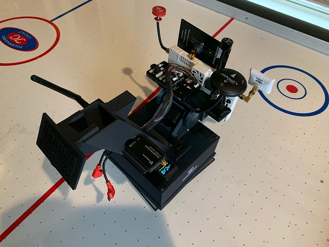
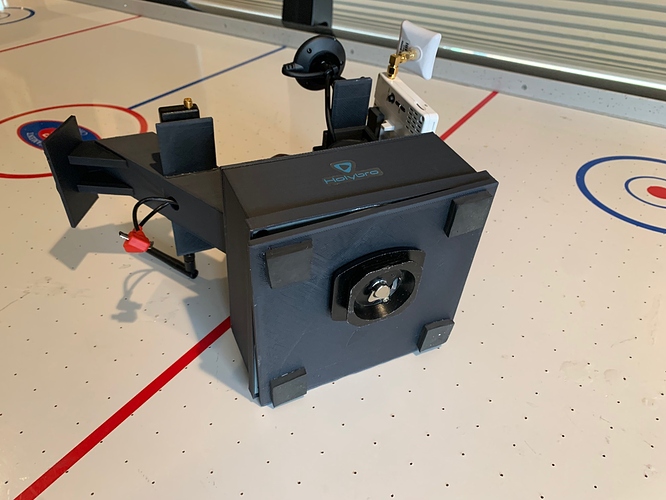
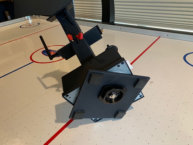
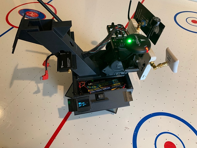
Here is a link to my GitHub with the .stl files, parts list, and parameters of the tracker I designed and built with a 3D printer.

All of my documentation is based on my setup using the following.

-MP 1.3.7
-Holybro Pixhawk 4 board with GPS
-AT 1.1 Stable Firmware on Windows
-Custom designed Antenna Tracker Frame, 3D printed with Carbon Fiber PLA

Key Items That Are Not Documented Well or Not Documented at All

  1. As soon as you power up the AT, it goes into Auto mode. You need to manually change the action menu and set to STOP in order to calibrate anything. Sometimes you may need to put it into manual mode, then STOP. I haven’t figured out if this is relative to firmware versions or just a oddity.

  2. AT will not start tracking a vehicle or lock onto it until it is a set distance from the unit. This parameter can be changed here - “Compass Distance_Min”
    a. When the tracker does lock on, it will make a long tone, and show “Armed” on the OLED screen if you have one connected.

  3. True Continuous Rotation Servos are the way to go, including for the pitch. I have not been able to get consistent results or tuning of PID’s with position servos, winch servos, or standard servos that have been modified to be continuous rotation. I high recommend you save yourself the hours or days of frustration and just start with high quality digital continuous rotation servos. HiTec HSR-2648CR servos from Servo City have been great so far. They are not that expensive ($40.00 each?) and well worth the initial expense vs the hours of attempts to get anything else to work correctly or consistently.

  4. Due to the nature of how AT processes data, movement, etc, If things are not properly set up right from the beginning, you can spend hours messing with parameters and tuning and finally get it to seem like its working properly, only to find out after you reboot it or try adjusting another parameter, that its suddenly a hot mess again. If you don’t know exactly what your doing or how one thing effects another ( I thought I did, but was very wrong, especially with PID’s here. I have 20+ years of 3D heli and Aero experience and this is a whole different world) it will become an infuriating experience. On a positive note, if you’re a determined freak about being able to figure things out to the end, its actually a great learning experience. I learned way more that I imagined or wanted to know about this whole autopilot deal because of this damn AT project.

Physical Hardware Setup/Layout

  1. Ensure that AHRS orientation is set properly.

  2. Make sure all compasses are mounted so that they rotate and tilt with the tracker as it moves.
    Calibrating the accelerometer, horizon, or compasses before they are mounted to their final permanent location will make life a nightmare trying to get it to work properly or consistently. ESPECIALLY PID’S! (I learned this the hard way after a full week of fighting to get anything to work) The best option is to have the entire AT rotate around a base. There is a link at the top of this post to the design I created and made with a 3D printer. It works great so far. There is also a file that lists all of the components I used to build it as well as links to the specific ones I bought. A cost breakdown PDF is at the bottom of this post. Depending on what components you may already have, the cost can be less than $100.00 or up to $500.00 if you need to purchase every individual component.

  3. If external compass is used, make sure its orientation is set properly.
    PX4/ArdP automatically makes external compasses priority. For example if your board has two internal compasses, and your GPS module as a compass as well, the board will set the ID’s as follows. Compass 0 = External GPS Compass, Compass 1 = Internal Compass, Compass 2 = Second Internal Compass.

Calibration Procedure for Accelerometer

a. Power up system and allow it to initialize.

b. Arm using safety button on GPS module.

c. Go to flight data screen and put into “STOP” mode using the “Action” menu. You have to click “set mode” after you select whatever option. Go back to Sensor Menu in Initial Setup and select “Calibrate Accel.” If nothing happens after you click “Calibrate Accel,” go back to Action Menu and make sure its in STOP mode, and is armed.

Calibration Procedure for Compass

a. Power up system and allow it to initialize.

b. Arm using safety button on GPS module.

c. Go to “Flight Data” screen and put into STOP mode using the “Action” menu. You have to click “set mode” after you select whatever option.

d. Go back to Initial Setup menu and select compass.

e. Select your board at the top, and make sure your external compass orientation and your board orientation are correct. (look at artificial horizon on flight screen and tilt AT unit to make sure horizon is moving the right direction)

f. Click on calibrate compass….You should see something happen. Green bars or digits appear. Follow standard compass calibration as documented for all other vehicles. If nothing happens after you click “Start Calibration,” go back to Action Menu and make sure its in STOP mode, and is armed.

Simulation Using Live Actual Tracker

  1. Open two separate instances of MP. If you have two or more screens, its super helpful. Otherwise you can just do a split screen. Its also ideal to adjust AT settings in real time if you have two separate Sik radio sets. Otherwise, you can connect the AT unit with USB or Bluetooth, just be carful of the rotation limits with the cable. You can always keep the simulated vehicle path limited to whatever your rotation limits with the USB cable are.

  2. Power up the AT unit and connect to MP if you wish. Otherwise, just let it do its thing.

  3. On the second instance of MP, click the simulation icon.

  4. The home location should be the last location MP had when you connected the AT unit. If not, move the map to your actual location, right click the mouse and select “Set Home Here”

  5. Select “Plane” For whatever reason, I can never get Multirotor or any of the other Sim vehicle options to work.

  6. In the Action Menu, click on “ARM/Disarm” It will probably though a few logging errors, but just ignore them.

  7. In the Action Menu, change the mode to “Takeoff” and click “Set Mode”

  8. Use your mouse and put it over a location that is directly in front of you, about 200-500 meters out. Right click the mouse and select “Fly to Here”

  9. Once the sim vehicle reaches this point, it should start to loiter in a circle.

  10. Change the loiter radius in the command box on the left of the screen to 200m.

  11. Hold down the Ctrl Key and the F Key to bring up the Temp Menu.

  12. Click on “Mavlink” and a serial Output Window will pop up.

  13. In the top drop down, Select the Com Port that your Sik Radio is connected to via USB.

  14. In the second drop down, select the baud rate for your Sik Radio. It’s most likely 57,600

  15. Your Antenna tracker should emit a long tone. This means that it has locked onto the vehicle’s Mavlink signal.

  16. Press the “Safety Button” on the AT GPS module. Be carful as it should come to life and start moving.

  17. Give the AT unit at least a couple minutes before you start adjusting anything. It will most likely go into scan mode first, then will lock onto the target location.
    From this point, you can start adjusting your AT settings for PID, and any other parameters. I highly suggest you unplug the pitch servo at first. Just focus on getting the Pan to function properly first. Once you have that dialed in, move onto the Pitch.

Antenna Tracker Cost Breakdown and Full Parts List Web 1.pdf (47.1 KB)

Posts: 2

Participants: 1

Read full topic

Measuring thrust of a quattrocopter: my measurements have brief thrust peeks

$
0
0

@peterst wrote:

Hi everyone,
I want to find out, which throttle translates into which thrust of my particular drone. Therefore I’ve built a test setup with a computer readable scale, which measures up to 5 kg. I’ve tied my drone onto a ballast weight (a water crate in my case) and put both onto the scale. Now I’ve connected the drone with MissionPlanner and performed a motor test on all motors, specifying the throttle in percent. The weight measured during the motors running is now the total weight at 0 throttle (copter + ballast + battery = 4750 g in my case) minus the thrust.
See the two graphs of weight (in gram equivalents) over time (in seconds since epoque 1970-01-01) for what I mean. The weight seems to overshoot quickly to a very short minimum at t=t0+4.9 s with m_measured=4644 g, and then reach a stable point at t>t0+1.4 s with m_measured=4684 g (t0=1.576685864E9 s). The following graph is for a 15 % throttle test run.
throttle_015_percent_191218T171744P512P0100_10sec

For more detail I zoomed in the overshoot in the following graph
throttle_015_percent_191218T171744P512P0100

Shouldn’t this be a nice stepresponse without this peek/overshoot? (as in Fig. 8 in [Yoon 2015])
I checked ArduCopter’s motor_test.cpp and the test performed seems to just give the ESCs the order to set a particular throttle value, given in PWM. Am I missing something here?
Could the overshoot come from the scale?

Yours,
Peter

Resources:
[Yoon 2015]
Yoon, Myunggon. “Experimental identification of thrust dynamics for a multirotor helicopter.” International Journal of Engineering Research and Technology 4.11 (2015): 206-209.

Posts: 2

Participants: 1

Read full topic


SITL GpsFixType is always GPS_FIX_TYPE_RTK_FIXED

$
0
0

@Asher wrote:

I am using the dronefleet/mavlink Java library to make my own GCS. I am trying to detect when the drone is ready to arm, so that I can then arm it.

I have a class that parses all GpsRawInt messages and is listening to see when the fixType on the message is greater than or equal to GPS_FIX_TYPE_3D_FIX. However, I have always noticed that the fix type reports itself as GPS_FIX_TYPE_RTK_FIXED. However, when I try to arm (if the copter hasn’t been on long enough) it says “PreArm: Need 3D Fix” in the status messages.

So is the SITL broken, or is there an alternate way to figure out if I have a 3D fix or not?

Thanks for any help.

Posts: 2

Participants: 2

Read full topic

Bebop2 Flashing milos linux installer

$
0
0

@Infinite_Crystals wrote:

Hi Everyone…

While I was trying to fix the focus on my bebop2 camera I boot it up, but the camera was not fitted on the frame only connected facing down.

Since then I only have black screen/no video
I tested bebop2camera on bebop1 and works just fine
and bebop1 camera on bebop2=black screen/no video
SkyController hdmi out same problem

Also tried Bebop2 WebAdmin and so many resets/calibration and even downgrade with no results yet…

Bebop2 failed to Flash after – payload flashing OK – with the following message (displayed through UART connection)

P7R3
P7MU Revision 2
Crystal Frequency: 26000000 Hz
RAM config name: Milos - Dual NT5CC128M16CP-DI - CL11, CWL8 @750MHz 750 Mhz
Milos rev: 2

but 0
USB platform : P7
Wait for connection…
USB host connected, wait for loading…
plf: loading E_TEXT section to addr 0x821e83e8 size 2546256… done.
plf: loading U_DATA section to addr 0x82000000 size 1999846… done.
plf: loading U_BOOTLOADER section to addr 0x80700000 size 291… done.
Executing…
Booting Linux…’ boxinit.serialno=P732P0BG0300008261D0 calib=0x0014003C mtdpa’
[ 0.000000] Booting Linux on physical CPU 0
[ 0.000000] Linux version 3.4.11+ (tpoussevin@colossus) (gcc version 4.6.3 (5
[ 0.000000] CPU: ARMv7 Processor [412fc097] revision 7 (ARMv7), cr=10c53c7d
[ 0.000000] CPU: PIPT / VIPT nonaliasing data cache, VIPT aliasing instructie
[ 0.000000] Machine: Milos board
[ 0.000000] P7 per device DMA memory regions:
[ 0.000000] 9ff00000:9fffffff: cast-nand.0
[ 0.000000] 9fe00000:9fefffff: ci_hdrc.0
[ 0.000000] 9fd00000:9fdfffff: ci_hdrc.1
[ 0.000000] Memory policy: ECC disabled, Data cache writealloc
[ 0.000000] On node 0 totalpages: 130304
[ 0.000000] free_area_init_node: node 0, pgdat c04b5f00, node_mem_map c096700
[ 0.000000] Normal zone: 1152 pages used for memmap
[ 0.000000] Normal zone: 0 pages reserved
[ 0.000000] Normal zone: 129152 pages, LIFO batch:31
[ 0.000000] PERCPU: Embedded 5 pages/cpu @c0def000 s6464 r0 d14016 u32768
[ 0.000000] pcpu-alloc: s6464 r0 d14016 u32768 alloc=8*4096
[ 0.000000] pcpu-alloc: [0] 0 [0] 1
[ 0.000000] Built 1 zonelists in Zone order, mobility grouping on. Total pa2
[ 0.000000] Kernel command line: boxinit.serialno=P732P0BG0300008261D0 cal
[ 0.000000] PID hash table entries: 2048 (order: 1, 8192 bytes)
[ 0.000000] Dentry cache hash table entries: 65536 (order: 6, 262144 bytes)
[ 0.000000] Inode-cache hash table entries: 32768 (order: 5, 131072 bytes)
[ 0.000000] Memory: 509MB = 509MB total
[ 0.000000] Memory: 504520k/504520k available, 19768k reserved, 0K highmem
[ 0.000000] Virtual kernel memory layout:
[ 0.000000] vector : 0xffff0000 - 0xffff1000 ( 4 kB)
[ 0.000000] fixmap : 0xfff00000 - 0xfffe0000 ( 896 kB)
[ 0.000000] vmalloc : 0xe0800000 - 0xff000000 ( 488 MB)
[ 0.000000] lowmem : 0xc0000000 - 0xe0000000 ( 512 MB)
[ 0.000000] .text : 0xc0008000 - 0xc0439dc0 (4296 kB)
[ 0.000000] .init : 0xc043a000 - 0xc0471940 ( 223 kB)
[ 0.000000] .data : 0xc0472000 - 0xc04b6a60 ( 275 kB)
[ 0.000000] .bss : 0xc04b6a84 - 0xc096651c (4799 kB)

p7: machine setup
[ 0.415717] p7: registering p7-pinctrl.0…
[ 0.416235] p7-pinctrl p7-pinctrl.0: loaded
[ 0.416260] p7: registering user_gpio.-1…
[ 0.416486] ------------[ cut here ]------------
[ 0.416513]WARNING: at /opt/tpoussevin/buildinstaller_last/kernel-p7/linux/)
[ 0.416526] sysfs: cannot create duplicate filename ‘/class/lcd’
[ 0.416561] [] (unwind_backtrace+0x0/0xf8) from [] (warn)
[ 0.416583] [] (warn_slowpath_common+0x50/0x60) from [] )
[ 0.416604] [] (warn_slowpath_fmt+0x30/0x40) from [] (sy)
[ 0.416624] [] (sysfs_add_one+0x90/0xa0) from [] (create)
[ 0.416643] [] (create_dir+0x60/0xbc) from [] (sysfs_cre)
[ 0.416669] [] (sysfs_create_dir+0x90/0xf4) from [] (kob)
[ 0.416690] [] (kobject_add_internal+0x94/0x1dc) from [])
[ 0.416718] [] (kset_register+0x20/0x3c) from [] (__clas)
[ 0.416739] [] (class_register+0xcc/0x1f4) from [] ()
[ 0.416762] [] (__class_create+0x48/0x6c) from [] (p7brd)
[ 0.416786] [] (p7brd_export_fb_positions+0x1c/0x148) from [<c0447)
[ 0.416813] [] (mykonos3x_init_mach+0x14/0x3bc) from [] )
[ 0.416834] [] (customize_machine+0x20/0x28) from [] (do)
[ 0.416853] [] (do_one_initcall+0x9c/0x168) from [] (ker)
[ 0.416879] [] (kernel_init+0x130/0x1cc) from [] (kernel)
[ 0.417004] —[ end trace 1b75b31a2719ed1c ]—
[ 0.417026] ------------[ cut here ]------------
[ 0.417044] WARNING: at /opt/tpoussevin/buildinstaller_last/kernel-p7/linux/)
[ 0.417060] kobject_add_internal failed for lcd with -EEXIST, don’t try to r.
[ 0.417087] [] (unwind_backtrace+0x0/0xf8) from [] (warn)
[ 0.417108] [] (warn_slowpath_common+0x50/0x60) from [] )
[ 0.417129] [] (warn_slowpath_fmt+0x30/0x40) from [] (ko)
[ 0.417149] [] (kobject_add_internal+0x1d8/0x1dc) from [)
[ 0.417172] [] (kset_register+0x20/0x3c) from [] (__clas)
[ 0.417192] [] (class_register+0xcc/0x1f4) from [] ()
[ 0.417212] [] (__class_create+0x48/0x6c) from [] (p7brd)
[ 0.417233] [] (p7brd_export_fb_positions+0x1c/0x148) from [<c0447)
[ 0.417255] [] (mykonos3x_init_mach+0x14/0x3bc) from [] )
[ 0.417274] [] (customize_machine+0x20/0x28) from [] (do)
[ 0.417293] [] (do_one_initcall+0x9c/0x168) from [] (ker)
[ 0.417314] [] (kernel_init+0x130/0x1cc) from [] (kernel)
[ 0.417326] —[ end trace 1b75b31a2719ed1d ]—

NAND device: Manufacturer ID: 0x98, Chip ID: 0xa1 (Toshiba NAND )
[ 0.655166] Scanning device for bad blocks
[ 0.736253] Bad eraseblock 768 at 0x000006000000

hub 1-0:1.0: USB hub found
[ 0.819307] hub 1-0:1.0: 1 port detected
[ 0.819931] gs_bind: controller ‘ci_pdata’ not recognized
[ 0.819955] gadget: Gadget Serial v2.4
[ 0.819974] gadget: g_serial ready
[ 0.820058] i2c /dev entries driver

mmc0: new high speed DDR MMC card at address 0001
[ 3.309730] mmcblk0: mmc0:0001 008GE0 7.28 GiB
[ 3.314712] mmcblk0boot0: mmc0:0001 008GE0 partition 1 4.00 MiB
[ 3.321030] mmcblk0boot1: mmc0:0001 008GE0 partition 2 4.00 MiB
[ 3.327528] usb 1-1: New USB device found, idVendor=0a5c, idProduct=bd1d
[ 3.335223] usb 1-1: New USB device strings: Mfr=1, Product=2, SerialNumber=3
[ 3.342816] usb 1-1: Product: Remote Download Wireless Adapter

[ 3.342933] mmcblk0: unknown partition table

[ 3.352978] usb 1-1: Manufacturer: Broadcom
[ 3.357000] usb 1-1: SerialNumber: 000000000001

[ 3.363993] mmcblk0boot1: unknown partition table

plf_boot_p7: last_call
external_flasher_run found 2 dir
umounting
/tmp/nand/mnt/update free 26MB(27MB) over 27MB
[ 39.788688] UBIFS: un-mount UBI device 4, volume 0
umounting
/tmp/nand/mnt/data free 8MB(8MB) over 8MB
[ 39.868905] UBIFS: un-mount UBI device 4, volume 1
umounting
/tmp/nand/mnt/@flasher free 10MB(10MB) over 10MB
umounting
/tmp/nand/mnt free 3MB(5MB) over 42MB
[ 40.207778] UBIFS: un-mount UBI device 3, volume 0
ubi_rename_vol on ubi1:1 main_boot -> 0
ubi_rename_vol on ubi1:0 alt_boot -> 0
sysfs_read_int on ubi1:-1 min_io_size=2048
ubi_get_vol_name on ubi1:0 alt_boot
sysfs_read_int on ubi1:0 data_bytes=3548404
sysfs_read_int on ubi1:0 reserved_ebs=67
sysfs_read_int on ubi1:0 usable_eb_size=126976
main size 3548404KB/8507392KB
sysfs_read_int on ubi1:1 data_bytes=4546428
sysfs_read_int on ubi1:1 reserved_ebs=55
sysfs_read_int on ubi1:1 usable_eb_size=126976
alt size 4546428KB/6983680KB
ubi_rename_boot on ubi1 kernel -> 0
[ 40.414395] UBI: mtd1 is detached from ubi1
ubi_detach on ubi1 : 0
sysfs_read_int on ubi2:-1 min_io_size=2048
[ 40.431393] UBI: mtd2 is detached from ubi2
ubi_detach on ubi2 : 0
sysfs_read_int on ubi3:-1 min_io_size=2048
[ 40.438080] UBI: mtd3 is detached from ubi3
ubi_detach on ubi3 : 0
sysfs_read_int on ubi4:-1 min_io_size=2048
[ 40.459563] UBI: mtd4 is detached from ubi4
ubi_detach on ubi4 : 0

can’t open /sys/class/ubi/ubi5/min_io_size device
can’t open /sys/class/ubi/ubi6/min_io_size device
can’t open /sys/class/ubi/ubi7/min_io_size device
can’t open /sys/class/ubi/ubi8/min_io_size device
can’t open /sys/class/ubi/ubi9/min_io_size device

install sucess : 25495488 bytes read
ui status : 11->20
get status 0
can’t open /sys/class/ubi/ubi1/min_io_size device
can’t open /sys/class/ubi/ubi2/min_io_size device
can’t open /sys/class/ubi/ubi3/min_io_size device
can’t open /sys/class/ubi/ubi4/min_io_size device
can’t open /sys/class/ubi/ubi5/min_io_size device
can’t open /sys/class/ubi/ubi6/min_io_size device
can’t open /sys/class/ubi/ubi7/min_io_size device
can’t open /sys/class/ubi/ubi8/min_io_size device
can’t open /sys/class/ubi/ubi9/min_io_size device
waitpid 59 59

halting
[ 46.579251] usb 1-1: USB disconnect, device number 2
[ 46.579411] p7-i2cm p7-i2cm.2: shutdown
[ 46.579425] p7-i2cm p7-i2cm.1: shutdown
[ 46.579435] p7-i2cm p7-i2cm.0: shutdown
[ 46.579467] Power down.
[ 46.622610] p7-i2cm p7-i2cm.0: i2c fifo mode without irq is not supported
[ 46.629364] p7-i2cm p7-i2cm.0: i2c fifo mode without irq is not supported
[ 46.636128] p7mu 0-0031: p7mu power off
[ 46.639814] p7-i2cm p7-i2cm.0: i2c fifo mode without irq is not supported
[ 3.378956] mmcblk0boot0: unknown partition table

Can you Guys please help me somehow to reflash the Bebop2?

Any advice would be appreciated…

Thank You

Posts: 1

Participants: 1

Read full topic

calibration problem with esc

$
0
0

@Arjun_Ramanujam wrote:

I am facing a problem with Pixhawk Board running Ardurover stack, recently i upgraded my transmitter to Flysky Noble. When I hold the throttle at max, Motor 1 starts spinning motor 2 is idle But, when i return the throttle to Zero position the 2nd Motor goes into calibration mode (3 beeps) and 2nd motor starts to spin at (0 Throttle).
Your suggestions will be helpful.
-Thankyou

Posts: 1

Participants: 1

Read full topic

LIDAR-Lite connection to Pixhawk

$
0
0

@adorus wrote:

I can’t make LIDAR-Lite v3 work with pixhawk1 on Copter-3.6.11 via PWM. Followed official instructions on https://ardupilot.org/copter/docs/common-rangefinder-lidarlite.html page. LIDAR is connected to AUX5 and configured to work in continuous mode. I can see narrow 3.3v pulses coming to “pin 54” AKA AUX5 with my oscilloscope. Parameters are set as follows:
RNGFND_TYPE = 5;
RNGFND_PIN = 54;
RNGFND_MAX_CM = 3500;
RNGFND_MIN_CM = 20;
RNGFND_SCALING = 1;
BRD_PWM_COUNT = 4
Autopilot does not see the LIDAR. MP always outputs “rangefinder_distance=0” in Status bar.
Previously I had ultrasonic rangefinder in that quad and it did function pretty well.
Can anyone please tell me what am I doing wrong?
P.S. Recently I looked at “Complete Parameters List” webpage more carefully and realized that I need to set RELAY_PIN = -1 (was 54) and RPM_PIN = -1 (was 54). Still not working…

Posts: 2

Participants: 2

Read full topic

Mavlink routing to onboard pixhawk

$
0
0

@raimondas wrote:

Hi,

Maybe someone could help me on implementation of mavlink routing.

Main idea to send data to raspberry pi which will be connected through telem2, also send a acknowledge.

I have plugin (C# visual studio) for the mission planner, which works great. Now I want to send through pixhawk data to raspberry pi.

So how to send data using mavlink router ? and how to receive it in rasberry pi ?
I have read this https://ardupilot.org/dev/docs/mavlink-routing-in-ardupilot.html
but it not explained for me, just gived tips what it is possible.

Practically I need some tips on functions in C# and in python for raspberry.
for example msg.send(telem2, data)

Thanks

Posts: 1

Participants: 1

Read full topic

Viewing all 46292 articles
Browse latest View live


<script src="https://jsc.adskeeper.com/r/s/rssing.com.1596347.js" async> </script>