BUILDING AN OPTIMIZED QUAD FRAME
In some way this blog is inspired on the very excellent job that did rob215x Robert Giordano in his post building a better quad frame and how to build the lightest ardupilot microquadcopter by Hugues. I must say that I won’t be able to make such nice video intros, but I will try to do my best with FEM and Engineering design.
What is the aim of the Project?
- The goal is to build a drone under 250 g. from scratch
- To make the design as light as possible, the frame will be designed under the basis of topology optimization
- The frame must be as light as possible while keeping enough strength and rigidity.
- The frame should support at least bad landings
- CAD, FEM and topology software should be open software
- Learning about material resistance
- Learning about anything related with drones
Project background
With topology optimization we should be able to answer these questions:
Why are most of the frames have a flat cross to support the motors?
Is the X frame the best design or would be better a carbon fibre shell?
What is Topology optimization?
Will the drone be able to fly?
Topology optimization
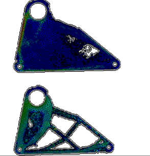
Topology optimization is a numerical method that optimizes material layout within a given space and within given loads and constrains to maximize the performance of the system (usually, the best relation between stiffness and weight). Let’s see an example.
![image]()
This kind of magic is nice but it is not so easy. First, the result could be difficult or much more expensive to manufacture. Second, this method is hard for computers. A small part takes hours to get a result on an average computer. The result is mesh dependent, and also variations on loads or constrains could show different or inaccurate results.
It would be great to bring this technology to the frame design, wouldn’t it?
Let’s Begin
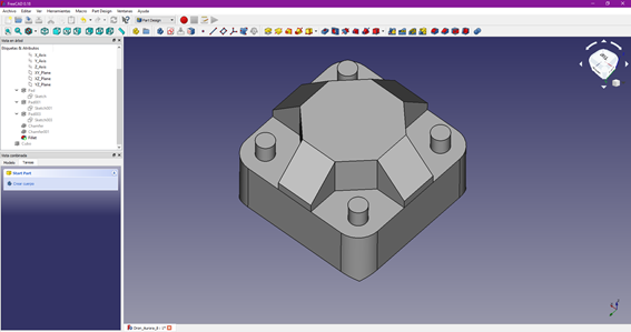
The first step is to design the maximum available space, so the computer has the possibility to use material anywhere. The blades produce a design constraint. To minimize the constraint a four blade propeller should be better, but efficiency should be worse, so I think I will use three blade propellers. Distance between opposite motors: 150 mm. (But should be scalable as smaller is lighter).
![image]()
This block is conservative, as I can be sure that no material outside this container would help to increase rigidity while lowering weight.
Second step: Generating the mesh.
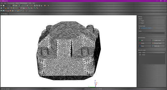
Topology optimization is very dependent on mesh quality and element size. Due to hardware limitations, I can only choose maximum element size of 4 mm. for a tetgen mesh. 2 mm. could give more detailed results, but my computer can’t stand it.
![image]()
Forces estimation
- Up: Each motor 1,50 N.
- Down: In a case of a free fall from one meter, the motors could generate a force down about 15 N. (Maybe too conservative).
- Lateral forces: Changes in yaw generate forces on the motors. These forces are lower than 1 N.
- Moments: The changes in the motor speed generate a moment in the z axis equals to 0.011 Nm
Solver
With these data, the computer can make its calculation. For this model took about 17 hours, and we got…
Conclusions
- This is what computer says, and of course, it can be wrong.
- If we assume that it is not completely wrong we can say:
- The best frame is a hybrid X.
- The arms that support the motors should not be flat. Instead, they should go up to the top of the frame.
- The design can be made with a 3D printer or with carbon fibre tubes.
- We could mount easily the FC, ESC, in the centre, under the top and therefore, the electronics will remain protected.
- It will be easy to hang the battery from the lower square. This square can also be used as a landing gear.
Next level: From design to reality
To be continued.


